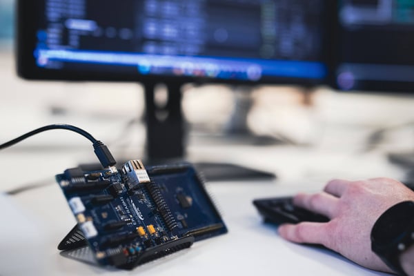
Techniques for measuring the elapsed time

It is mandatory for embedded systems to keep the execution time of a specific code shorter than the required time. The processing speed can be of crucial importance for an application, and the speed can be improved by using new algorithms or applying compiler optimizations. However, before trying to improve the performance of your code, you might want to measure the actual processing speed.

It is popular to use GPIO pins and oscilloscopes to measure the timing, and that is of course a valid and realistic approach. However, you can measure the elapsed time easily and more precisely by using functionality available in your MCU and development tools.

In this article, we introduce three basic techniques and a couple of more advanced techniques to measure the elapsed time with an ARM Cortex-M3/M4/M33/M7 device and IAR Embedded Workbench for ARM.

Technique 1: Using Log Breakpoint

If you only need a rough measurement, you can use a Log Breakpoint. When the code where the log breakpoint has been set is executed, the computer time will be displayed to the debug log window.

Features

  • No need to modify source code
  • Using a log breakpoint
  • The accuracy is one second

How to enable a log breakpoint

Right click the code for which you would like to know the executed time, and select Toggle Breakpoint (Log).

Measuring elapsed time 1

You will see the breakpoint marked with L:

Measuring elapsed time 2This code is a timer interrupt handler, which is triggered every one second. The output of the execution can be seen in the Debug Log window:

Measuring elapsed time 3

Time of Execution, corresponding source code and the count of the call are displayed.

This technique is not suitable for precise measurement, but it is very easy to use. You can also, for example, loop the target function a thousand times and measure the before and after time to get the elapsed time.

Technique 2: Using CycleCount register of the MCU

Recent MCUs often have a register to display elapsed cycles. ARM Cortex-M3/4/7 devices provide a register called CYCLECOUNTER.
Getting CYCLECOUNTER of two code points, and using the CPU clock, you can calculate the actual execution time. For example, if the CPU is running at 100MHz, you can divide by 100,000,000 to get the number of seconds passed.

Features

  • No need to modify source code
  • The accuracy is one CPU cycle unit
  • Support status depends on the MCU

IAR Embedded Workbench for ARM expands the functionality of CYCLECOUNTER so that you can easily see the differences of CYCLECOUNTER using the CCSTEP register.

How to use CYCLECOUNTER

Open the Register window.

Measuring elapsed time 4

Select CPU Registers.

Measuring elapsed time 5

CYCLECOUNTER is the elapsed cycle from start, and CCSTEP is the elapsed cycle from the last displayed timing.

Measuring elapsed time 6

By clicking Step Over, you increase the CYCLECOUNTER and the difference is shown as CCSTEP.

Measuring elapsed time 7

424(Current CYCLECOUNTER) – 416(Previous CYCLECOUNTER) = 8(Current CCSTEP)

CYCLECOUNTER is provided by ARM Cortex-M3 MCUs but disabled in IAR Embedded Workbench for ARM as a default. If you use I-jet, CYCLECOUNTER will be enabled. If you use another debugging probe and CYCLECOUNTER values are not updated, try setting the CYCCNTENA bit in the DWT Control register (DWT_CTRL.CYCCNTEN) which can be found in the Data Watchpoint and Trace register window.

Measuring elapsed time 8

The CYCLECOUNTER is easy to use and provides precise measurements. If you need to get the actual time, divide by the CPU clock. The CYCLECOUNTER can be different in pipeline or cache conditions. It is recommended not to measure only one or two instructions, but instead ten or more instructions to get more precise data.

Technique 3: Using the MCU timer

The timer is an important feature for the MCU to execute periodical processes. Often, you use the timer to get an interrupt by count-up or countdown timers. You can also measure the elapsed time by reading the count timer.

Features

  • Need to modify source code
  • Timer configuration
  • Code to access timer value
  • Can get cycle unit measurements
  • Timer configurations are different for each MCU, but you can use a common approach

How to use the MCU timer

First, you need to consider the clock source and pre-scaler. If the pre-scaler is 10, each 10 clock source cycle, the timer counter will be counted up or down. If the Clock source is the same as the CPU clock, the pre-scaler is 1000, the CPU clock is 100MHz and the Timer count difference is 100, then you can get 0.001 sec, so 1 ms as the elapsed time.

unsigned int cnt1 = 0;
unsigned int cnt2 = 0;

 cnt1 = TIM3->CNT;
 func();
 cnt2 = TIM3->CNT;
 printf("cnt1:%u cnt2:%u diff:%u \n",cnt1,cnt2,cnt2-cnt1);

The result is as follows:

cnt1:370 cnt2:740 diff:370

If you use the time of an actual function, the Timer count can be reset by an interrupt and therefore we recommend using the timer only for measurements. While the code execution is halted at a breakpoint, the timer count can be running. Therefore, you should store the count value to a variable.

The ARM Cortex-M SystickTimer count is stopped while the CPU is not running. That makes is useful for measuring time, especially for ARM Cortex-M0/M0+ MCUs which do not have the CYCLECOUNTER register.

Technique 4: Using Data Log breakpoint

Data Log breakpoint is a powerful debugging feature for ARM Cortex-M3 and M4 devices. Using a debug probe that supports SWD/SWO, such as I-jet, you can capture a log of data access and timestamps in real time.

Before starting the debug session, we must setup the debug probe to SWD and SWO:
Measuring elapsed time 9Measuring elapsed time 10

Here is the example code:

static int data_main = 0;
static int data_systick = 0;

void Delay(Int32U Dly)
{
  for(volatile Int32U j = Dly; j; j--) { }
}

void SysTick_Handler(void)
{
  data_systick += 10;
}

void main(void)
{
  SystemInit();
  SysTick_Config(900000);
  SysTick_CLKSourceConfig(SysTick_CLKSource_HCLK_Div8);
  
  while(1)
  {
    Delay(100000);
    data_main++;
  }
}
 

In the main loop, data_main will be incremented after some delay. There is also the SysTick timer interrupt handler, which increments data_systick. Using Data Log Breakpoint, you can see the value of variables and access timing.

How to set the Data Log Breakpoint

Right-Click data_main in the editor window and select Set Data Log Breakpoint for 'data_main'.

Measuring elapsed time 11

You can also set Data Log Breakpoint for data_systick:

Measuring elapsed time 12

Now, start the C-SPY debug session:

Measuring elapsed time 13

Display the Data Log Breakpoint by selecting View->Breakpoints.

Measuring elapsed time 14

You will see the Data Log breakpoints in the list window.

Measuring elapsed time 15

The Data log is disabled as default. To enable the Data Log, open the Data Log window (I-jet > Data Log).

Measuring elapsed time 16

Right-click in the window and select Enable.

Measuring elapsed time 17When the target is running and accesses the two variables, the value and time is shown in the Data Log window.

Measuring elapsed time 18

You can also show the time as CPU cycle-based counts.

Measuring elapsed time 19

If we look at the time of 'data_main' W:12 and 'data_main' W:13, the difference is 866,768 cycle. So we can conclude that "Delay(100000)" costs about 866,768 cycles.

Originally, Data Log is for tracing data accesses. But it is a practical approach to use it for tracing code execution and timing as well.

Note:

  • The variables for data log breakpoints should have fixed addresses such as static variables or global variables.
  • There is no extra overhead for data log.
  • Based on ARM Cortex-M3/M4 specifications, the maximum number of data log breakpoints is four.

Technique 5: Using Event log

Event log is another debugging feature for ARM Cortex-M3/M4 devices. You can add event code in your application, and each time the code is executed, an Event log will be generated.

Modify a few lines of data log test code:


static int data_main = 0;
static int data_systick = 0;

#include <arm_itm.h>

void Delay(Int32U Dly)
{
  for(volatile Int32U j = Dly; j; j--) { }
}

void SysTick_Handler(void)
{
  data_systick += 10;
  ITM_EVENT32_WITH_PC(2,data_systick);
}

void main(void)
{
  SystemInit();
  SysTick_Config(900000);
  SysTick_CLKSourceConfig(SysTick_CLKSource_HCLK_Div8);
  while(1)
   {
     Delay(100000);
     data_main++;
     ITM_EVENT32_WITH_PC(1,data_main);
   }
}

 To generate the event log, the arm_itm.h file must be included.

ITM_EVENT32_WITH_PC is a macro defined in the header file, the first parameter is the channel and the second parameter is a data: data can be const value or a variable, channel can be 1 to 4.

To see the Event Log in debug session, open and enable the Event Log window.

Measuring elapsed time 20

Right-Click the Event Log window and select Enable.

Measuring elapsed time 21

Now, you can run the application and will see the event log data.

Measuring elapsed time 22

The data for channel 1 is displayed in the ITM1 column, and data for channel 2 is displayed in the ITM2 column. You can also see the time stamp and Program Counter of the event log macro code.

You can also change the view to show cycles.

Measuring elapsed time 23

The elapsed time between ITM1 56 and 57 is 48,541,271 – 47,674,478 = 866,793. This number is almost the same as the number we saw with Data Log.

Note:

  • The ITM event macro has a small overhead of code size and execution time. It is suitable for measuring code execution time as long as the time is not too small.
  • In the arm_itm.h file, other macros such as ITM_EVENT16_WITH_PC, ITM_EVENT16 are available. If you do not need Program Counter information, use ITM_EVENT8, 16, 32 to reduce the overhead.

The data can be saved as text file for further analysis.

Viewing the Data Log and Event Log in the Timeline Window

The Data Log and the Event log can be viewed in the Timeline window using the same time scale. You can visualize how each data access and ITM event happened and measure the time differences.

Open I-jet /JTAGjet > Timeline window.

Measuring elapsed time 24

You will see several lanes. Right-Click the Data Log pane and Events pane and select Enable.

Measuring elapsed time 25

You can change the time scale by right-clicking and selecting Zoom.

Measuring elapsed time 26

Now, you can see the Data Log data and ITM Event data graphically with timestamps.

Measuring elapsed time 27

If you mouse-over the data, you get the detailed time information.

Measuring elapsed time 28

If you select a time range, you can see the time information for that range.

Measuring elapsed time 29

Conclusion

Before trying to improve the code performance, you should set up a measurement environment. To measure the elapsed time, there are generic techniques as well as MCU-specific techniques. You can adapt and improve the techniques described in this article to suit your evaluation, development and debugging needs. Please refer to the C-SPY Debugging Guide from the Help menu in IAR Embedded Workbench to learn more about the functionality described here.

We do no longer support Internet Explorer. To get the best experience of iar.com, we recommend upgrading to a modern browser such as Chrome or Edge.