Creating a bootloader for Cortex-M
Technical Note 160822
Architectures:
ARM
Component:
general
Updated:
8/17/2020 1:32 PM
Introduction
This Technical Note provides guidelines on how to create a bootloader using IAR Embedded Workbench for ARM. Most of the recommendations in the Technical Note are general, although the example project is for a Cortex-M microprocessor (specifically STMicroelectronics STM32L152VB).
Discussion
When creating a bootloader, there are some things to consider regarding project setup, and the execution handover from the bootloader to the application. See the example project for STM32L152VB and follow the considerations below. Note that for clarity, this Technical Note does NOT describe how to perform a “live update” (IAP – in application programming) of the application, or how to configure communication interfaces, although this is a common feature in bootloaders.
General considerations
- Create separate projects – one for the bootloader and one for the application. The two projects can be placed in the same workspace. By keeping the projects separate, you make sure that code and library functions are not being shared between the bootloader and the application.
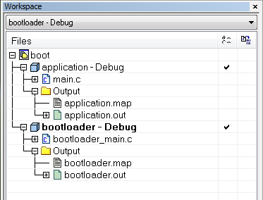
- Check the flash memory block size (the smallest erasable unit of the flash memory). The divide between the bootloader and application must be on a flash block boundary, otherwise you risk erasing parts of the application or bootloader when you replace one of them.
- Any hardware initialization should normally only be performed once, most often by the bootloader. Make sure that the application does not re-initialize the hardware unless that is what you want.
- Before the bootloader hands over execution to the application, make sure to:
- Disable interrupts – to avoid unexpected interrupts during application startup.
- Configure/reset the stack pointer – so that the application’s stack memory is not already used up by the bootloader.
- Configure the
VTORregister – so that interrupts are handled by the application – not the bootloader.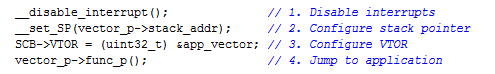
Debugging considerations
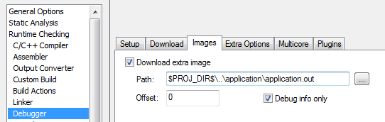
Debugging the bootloader and the application at the same time is possible, but can be tricky, for example because they both contain a main function. To make the debugger aware of the two applications, choose Project > Options > Debugger > Images to load debug information from the other project’s ELF output file.
Make sure that the option Run to: main is disabled on the Debugger Setup page, to avoid any confusion about which of the main functions to run to (the main function in the bootloader or the main function in the application).
You can also tell the debugger exactly which main function to run to, by using the <module>\<function> syntax. See Technical Note 45813. In this example, you can use Run to: bootloader_main\main.
After downloading, the debugger will by default start execution at the address specified in the symbol called __vector_table. When you debug the bootloader and the application at the same time, the following message might be displayed:
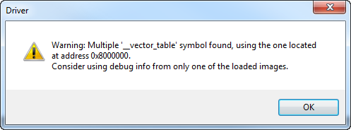
To guide the debugger to the correct __vector_table symbol, you can explicitly specify where the bootloader’s vector table is located. Choose Project > Options > Debugger > Extra Options and specify:
--drv_vector_table_base=0x08000000
When you are debugging, use the View > Images window to select the application currently in scope, to avoid problems with conflicting symbol names in the two applications.
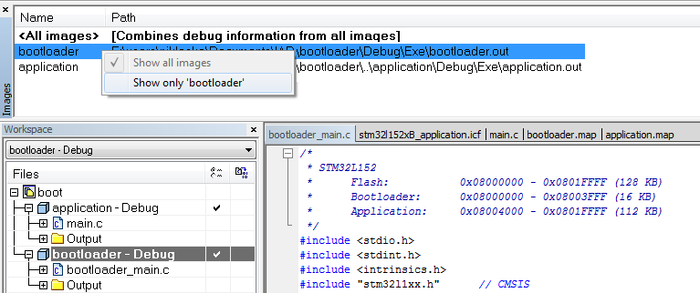
When single-stepping over the actual jump from the bootloader to the application, remember to change the currently loaded debug info (in the Images window).
Flash writing considerations
To download the application and bootloader to flash memory, there are many alternatives. Because the bootloader and application are placed in separate projects, they can be downloaded individually from each project. As an alternative, you can download them both to flash memory at the same time, for example by using the linker to include an application binary in the bootloader project (or vice versa). Choose Project > Options > Linker > Input to accomplish this.
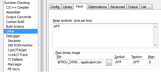
In the linker configuration file, the application binary is placed in flash memory with:
place at address mem: app_vector { readonly section .APP };
See the example project for more details. The project can be tested using the C-SPY Simulator driver or on a STM32 target device, using I-jet.
The example project also exists in an adapted form, in technical note 11578. The adaptation is to build the bootloader so that it, (as much as possible), runs in RAM.
Limitations
The details in this Technical Note applies to Cortex-M cores with the VTOR register.
- Cortex-M3 (and higher) has the
VTORregister. - The VTOR register is optional in Cortex-M0+ and in Cortex-M23, so check the device documentation to see if the chip vendor has included
VTOR, or not. - If the core in use is a Cortex-M0 or Cortex-M1, the parts of this Technical Note relating to
VTORdoes not apply, as there is noVTORregister.
Conclusion
When you create a bootloader, you must consider a few things concerning project structure and the actual jump from the bootloader into the application. This Technical Note aims to serve as a general guideline for creating a bootloader using IAR Embedded Workbench for ARM. To get more information about debugger windows, options and the __vector_table symbol, choose Help > C-SPY Debugging Guide. For examples on how to write to flash memory from an application, choose Help > Information Center > Example Projects for your specific device.
All product names are trademarks or registered trademarks of their respective owners.